September 4, 2019
Battery Management for Large-Scale Energy Storage (Part 2)
Part 2 of 4:
Open Wire Detection
The accuracy of battery data and the sharing of that data across BMS modules are of critical importance in ensuring precise battery management.
There can be hundreds or even thousands of sense wires in a large-scale energy storage system, including sense connections between cells within a battery module. A loose or unconnected sense wire between the cells in a module, between the batteries and BMS, or among the many wires that connect BMS modules to each other, could result in the BMS operating with incorrect data and sharing that faulty data with other ESS components. This can lead to battery damage and safety issues. For example:
- The PCS could overcharge or over-discharge cells.
- The PCS could provide or draw a damaging level of current during the charge or discharge process.
- Thermal management systems could fail to initiate in a timely fashion in response to overheating cells.
- The BMS may fail to disconnect the battery when safety thresholds have been exceeded.
When designing energy storage systems, it is recommended to include a mechanism for ensuring that the BMS is receiving data from correctly connected sense wires, and a way of verifying that voltage, current, and temperature data from every cell are propagating correctly across all battery management modules.
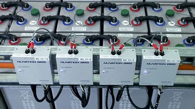
Nuvation Energy battery management systems include a feature called Open Wire Detection which detects damaged, loose, disconnected, or incorrectly torqued sense wires.
This includes identifying connection quality issues in sense wires between cells within the many battery modules in the energy storage system. Nuvation’s BMS also includes a self-diagnostic function that auto-initiates during the BMS start-up sequence and:
- Verifies that all sensor data is propagating correctly across all battery management modules.
- Reports any errors by generating a system Fault through the BMS Operator Interface.
- Suspends the BMS startup sequence until any errors have been resolved.
- Automatically resumes the startup sequence from where it left off after issues have been resolved.


Energizing and De-Energizing the Contactors
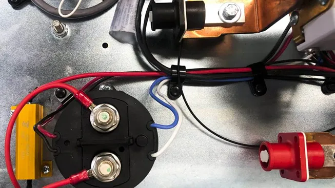
Since most safety situations arise and escalate while energy is flowing through batteries, disconnecting the batteries from the flow of energy is a quick and highly effective way to de-escalate an emerging safety issue. If batteries begin to operate outside of safe performance parameters, the BMS will disconnect the batteries by de-energizing the contactors connecting the batteries to the power path. Contactors are physical switches in the path of the energy flow. The BMS is able to open and close a contactor by de-energizing (opens the contactor) and energizing (closes the contactor) magnetic coils inside the contactor unit. Nuvation Energy’s battery management system can provide power to the contactor coils directly, which strengthens its reliability as a safety system by enabling it to de-energize the contactors without assistance from any additional components.
Uni-directional contactors must be installed in a direction that is aligned with the direction the current is flowing, otherwise their power rating during connection and disconnection can be as much as 50% lower. Bi-directional contactors have the same power rating for both directions of current flow during connection and disconnection.
When either type of contactor is energized it has the same power rating in both directions. One design approach when designing Stack Switchgear is to put a separate contactor at each end of the power path (i.e. one on the side of the positive terminal and one on the side of the negative terminal), and to first disconnect the contactor that is aligned with the direction as the flow of current (i.e. charging or discharging). One can also choose to implement only a single bi-directional contactor, but Nuvation Energy has made the choice of creating the redundant safety feature of designing in two separate contactors so that if one fails, the other can sever the connection.
Nuvation Energy’s battery management system allows the alignment of the contactor to be programmed into the BMS. This enables the BMS to intelligently disconnect the battery from the flow of energy by first opening the contactor that is aligned with the direction in which the current is flowing. It will then open the second contactor to completely disconnect the battery stack from all potential power sources, for added safety.
Thermal Runaway Mitigation
Thermal runaway is a condition that can occur in several battery types, including lithium-ion and some lead-acid batteries. It is a condition where a rapid rise in the temperature of one or more battery cells causes a reaction within the cell that triggers further increases in temperature.
Causes of thermal runaway include a short circuit within or outside of the battery, overcharging, and the excessive application of current during charging. Once initiated, this reaction can continue and cascade to other cells in the pack and eventually become uncontrollable. This can lead to battery fires and even explosions.
There are multiple thermal management mechanisms in an energy storage system. These include batteries themselves, which are designed to dissipate heat and contain thermal reactions. However, the action most likely to prevent a thermal runaway event is to recognize when individual cells are approaching operational limits and to disconnect the batteries from the power path.
A thermal runaway event can take place within a short period of time, but thermal runaway reactions tend to begin only after cell temperatures have risen well beyond the battery manufacturer’s nominal operating temperature ranges.

Damaged batteries however, can go into thermal runaway while being operated within their nominal parameters. One way to damage batteries is by cycling them below their rated operating temperature. At low temperatures, a number of chemical reactions can occur within the battery which can cause irreversible damage to the cells. For example, the image below shows the nominal temperature range of a typical lithium-ion battery. During testing at the University of Waterloo, an LFP cell was deliberately operated at -30°C for several hours. This extended operation below nominal temperatures damaged the cell. In subsequent operation under nominal conditions a short circuit developed in the battery, due the the damage caused during low-temperature testing. The short circuit triggered a thermal runaway event within 5 seconds of occurring, while the battery was being operated within nominal operating parameters.

This lab test illustrates the importance of ensuring the battery is kept within its operating limits throughout its entire lifetime. Although a battery might appear to be functioning normally, any cycling outside the nominal operating range can damage the battery internally. The role of a battery management system is to ensure that the battery never exceeds its nominal temperature, voltage and current limits. This will help preserve battery life and prevent thermal runaway events from occurring.
Up Next
- Protecting the Battery
- Warnings, Faults, & User-Defined Thresholds
- Communicating with Energy Controllers
- Power Conversion Systems (PCS)
- Energy Controllers
- Environmental Controls
- Cell Balancing

